Controlling an LED
You are now ready to build your first Blynk application that can be used to control an LED attached to the Raspberry Pi from your smartphone or tablet. The application consists of the following components:
- Blynk app running on your smartphone or tablet
- C++ project running on Raspberry Pi
- Blynk cloud
Things you need
You will need following things to build the circuit:
- Raspberry Pi 3 board
- A breadboard
- An LED - Basic Red 5 mm (https://www.sparkfun.com/products/9590)
- A 330 Ohm 1/6 Watt PTH resistor (https://www.sparkfun.com/products/11507) color coded orange, brown, gold
- Two male-female jumper wires
Building the circuit
The following diagram shows how you can connect an LED to the BCM_GPIO pin 18 (physical pin 12) of the Raspberry Pi 3:
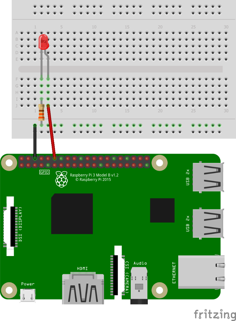
LED connected to the BCM_GPIO 18 of the Raspberry Pi 3
Connect the positive leg (the longer leg) of the LED to the physical pin 12 (BCM_GPIO PIN 18) of the Raspberry Pi.
Connect the negative leg (the shorter leg or the leg adjacent to the flat edge on the...