Most readers are probably more familiar with the x86 architecture, which implements the CISC design, and may wonder—why do we actually need something else? The main advantage of RISC architectures is that processors that implement them generally require fewer transistors, which eventually makes them more energy and heat efficient and reduces the associated manufacturing costs, making them a better choice for portable devices. We start our introduction to RISC architectures with ARM for a good reason—at the moment, this is the most widely used architecture in the world.
The explanation is simple—processors implementing it can be found on multiple mobile devices and appliances such as phones, video game consoles, or digital cameras, heavily outnumbering PCs. For this reason, multiple IoT malware families and mobile malware targeting Android and iOS platforms have payloads for ARM architecture; an example can be seen in the following screenshot:
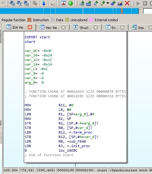
Figure 5: Disassembled IoT malware targeting ARM-based devices
Thus, in order to be able to analyze them, it is necessary to understand how ARM works first.
ARM originally stood for Acorn RISC Machine, and later for advanced RISC Machine. Acorn was a British company considered by many as the British Apple, producing some of the most powerful PCs of that time. It was later split into several independent entities with Arm Holdings (currently owned by SoftBank Group) supporting and extending the current standard.
There are multiple operating systems supporting it, including Windows, Android, iOS, various Unix/Linux distributions, and many other lesser known embedded OSes. The support for a 64-bit address space was added in 2011 with the release of the ARMv8 standard.
Overall, the following ARM architecture profiles are available:
- Application profiles (suffix A, for example, the Cortex-A family): This implements a traditional ARM architecture and supports a virtual memory system architecture based on a Memory Management Unit (MMU). These profiles support both ARM and Thumb instruction sets (as discussed later).
- Real-time profiles (suffix R, for example, the Cortex-R family): This implements a traditional ARM architecture and supports a protected memory system architecture based on a Memory Protection Unit (MPU).
- Microcontroller profiles (suffix M, for example, the Cortex-M family): This implements a programmers' model and is designed for integration into Field Programmable Gate Arrays (FPGAs).
Each family has its own corresponding set of associated architectures (for example, the Cortex-A 32-bit family incorporates ARMv7-A and ARMv8-A architectures), which in turn incorporate several cores (for example, ARMv7-R architecture incorporates Cortex-R4, Cortex-R5, and so on).
Here, we will cover both the original 32-bit and the newer 64-bit architectures. There were multiple versions released over time, starting from the ARMv1. In this book, we will focus on the recent versions of them.
ARM is a load-store architecture; it divides all instructions into the following two categories:
- Memory access: Moves data between memory and registers
- Arithmetic Logic Unit (ALU) operations: Does computations involving registers
ARM supports arithmetic operations for adding, subtracting, and multiplying, and some new versions, starting from ARMv7, also support division operations. It supports big-endian order, and uses the little-endian format by default.
There are 16 registers visible at any time on the 32-bit ARM: R0-R15. This number is convenient as it takes only 4 bits to define which register is going to be used. Out of them, 13 (sometimes referred to as 14 including R14 or R15, also R13) are general-purpose registers: R13 and R15 each have a special function while R14 can take it occasionally. Let's have a look at them in greater detail:
- R0-R7: Low registers are the same in all CPU modes.
- R8-R12: High registers are the same in all CPU modes except the Fast Interrupt Request (FIQ) mode not accessible by 16-bit instructions.
- R13 (also known as SP): Stack pointer—points to the top of the stack, and each CPU mode has its own version of it. It is discouraged to use it as a GPR.
- R14 (also known as LR): Link register—in user mode it contains the return address for the current function, mainly when BL (Branch with Link) or BLX (Branch with Link and eXchange) instructions are executed. It can also be used as a GPR if the return address is stored on the stack. Each CPU mode has its own version of it.
- R15 (also known as PC): Program counter, points to the currently executed command. It's not a GPR.
Altogether, there are 30 general-purpose 32-bit registers on most of the ARM architectures overall, including the same name instances in different CPU modes.
Apart from these, there are several other important registers, as follows:
- Current Program Status Register (CPSR): This contains bits describing a current processor mode, a processor state, and some other values.
- Saved Program Status Registers (SPSR): This stores the value of CPSR when the exception is taken, so it can be restored later. Each CPU mode has its own version of it, except the user and system modes, as they are not exception-handling modes.
- Application Program Status Register (APSR): This stores copies of the ALU status flags, also known as condition code flags, and on later architectures, it also holds the Q (saturation) and the greater than or equal to (GE) flags.
The number of Floating-Point Registers (FPRs) for a 32-bit architecture may vary, depending on the core, up to 32.
ARMv8 (64-bit) has 31 general-purpose X0-X30 (R0-R30 notation can also be found) and 32 FPRs accessible at all times. The lower part of each register has the W prefix and can be accessed as W0-W30.
There are several registers that have a particular purpose, as follows:
| Name |
Size |
Description |
|
XZR/WZR
|
64/32 bits, respectively
|
Zero register
|
|
PC
|
64 bits
|
Program counter
|
|
SP/WSP
|
64/32 bits, respectively
|
Current stack pointer
|
|
ELR
|
64 bits
|
Exception link register
|
|
SPSR
|
32 bits
|
Saved processor state register
|
ARMv8 defines four exception levels (EL0-EL3), and each of the last three registers gets its own copy of each of them; ELR and SPSR don't have a separate copy for EL0.
There is no register called X31 or W31; the number 31 in many instructions represents the zero register, ZR (WZR/XZR). X29 can be used as a frame pointer (which stores the original stack position), and X30 as a link register (which stores a return value from the functions).
Regarding the calling convention, R0-R3 on the 32-bit ARM and X0-X7 on the 64-bit ARM are used to store argument values passed to functions R0-R1 and X0-X7 (and X8, also known as XR indirectly) to hold return results. If the type of the returned value is too big to fit them, then space needs to be allocated and returned as a pointer. Apart from this, R12 (32-bit) and X16-X17 (64-bit) can be used as intra-procedure-call scratch registers (by so-called veneers and procedure linkage table code), R9 (32-bit) and X18 (64-bit) can be used as platform registers (for OS-specific purposes) if needed, otherwise they are used the same way as other temporaries.
As previously mentioned, there are several CPU modes implemented according to the official documentation, as follows:
|
Operating mode name
|
Abbreviation
|
Description |
|
User
|
usr
|
Usual program execution state, used by most of the programs
|
|
Fast interrupt
|
fiq
|
Supports data transfer or channel process
|
|
Interrupt
|
irq
|
Used for general-purpose interrupt handling
|
|
Supervisor
|
svc
|
Protected mode for the OS
|
|
Abort
|
abt
|
Is entered after a data or instruction Prefetch Abort
|
|
System
|
sys
|
Privileged user mode for the OS. Can be entered only from another privileged mode by modifying the mode bit of the CPSR
|
|
Undefined
|
und
|
Is entered when an undefined instruction is executed
|
There are several instruction sets available for ARM processors: ARM and Thumb. A processor that is executing ARM instructions is said to be operating in the ARM state and vice versa. ARM processors always start in the ARM state, and then a program can switch to the Thumb state by using a BX instruction. Thumb Execution Environment (ThumbEE) was introduced relatively recently in ARMv7 and is based on Thumb, with some changes and additions to facilitate dynamically generated code.
ARM instructions are 32 bits long (for both AArch32 and AArch64), while Thumb and ThumbEE instructions are either 16 or 32 bits long (originally, almost all Thumb instructions were 16-bit, while Thumb-2 introduced a mix of 16- and 32-bit instructions).
All instructions can be split into the following categories according to the official documentation:
| Instruction Group |
Description |
Examples |
|
Branch and control
|
These instructions are used to:
- Follow subroutines
- Go forward and backwards for conditional structures and loops
- Make instructions conditional
- Switch between ARM and Thumb states
|
B: Branch
BX: Branch and exchange instruction set
CBZ: Compare against zero and branch
IT: If-then, makes up to four following instructions conditional (32-bit Thumb)
|
|
Data processing
|
Operate with GPRs, support data movement between registers and arithmetic operations
|
ADD: Add
MOV: Move data
MUL: Multiply
|
|
Register load and store
|
Move data between registers and memory
|
LDR: Load register (1 byte)
STRB: Store register (1 byte)
SWP: Swap register and memory content
|
|
Multiple register load and store
|
Load or store multiple GPRs from or to memory
|
STM/LDM: Store and load multiple registers to and from memory
PUSH/POP: Push and pop registers to and from the stack
|
|
Status register access
|
Move the content of a status register (CPSR or SPSR) to or from a GPR
|
MRS: Move the contents of the CPSR or SPSR to a GPR MSR; load specified fields of the CPSR or SPSR with an immediate value or another register's value
|
|
Coprocessor
|
Extend the ARM architecture; enable control of the system control coprocessor registers (CP15)
|
CDP/CDP2: Coprocessor data operations
|
In order to interact with the OS, syscalls can be accessed using the Software Interrupt (SWI) instruction, which was later renamed the Supervisor Call (SVC) instruction.
See the official ARM documentation (a link is provided later) to get the exact syntax for any instruction. Here is an example of how it may look:
SVC{cond} #imm
The {cond} code in this case will be a condition code. There are several condition codes supported by ARM, as follows:
- EQ: Equal to
- NE: Not equal to
- CS/HS: Carry set or unsigned higher or both
- CC/LO: Carry clear or unsigned lower
- MI: Negative
- PL: Positive or zero
- VS: Overflow
- VC: No overflow
- HI: Unsigned higher
- LS: Unsigned lower or both
- GE: Signed greater than or equal to
- LT: Signed less than
- GT: Signed greater than
- LE: Signed less than or equal to
- AL: Always (normally omitted)
An imm value stands for the immediate value.