


Generating G-code
G-code is generated by your slicer. The slicer is a program that takes the file of your 3D model and slices it up into many layers. A model created for 3D printing is constructed by a contiguous surface of triangles. This forms the entire skin of your model, without any gaps or overlapping.
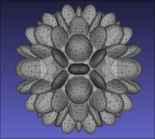
The following image is a model created with TopMod.
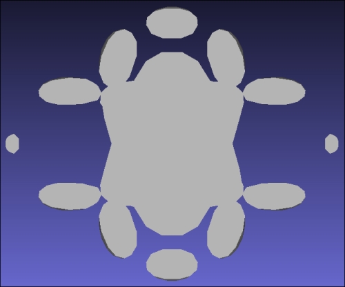
When the slicer program slices the model, it generates a perimeter of each Z layer. A sliced layer is illustrated in the following image:
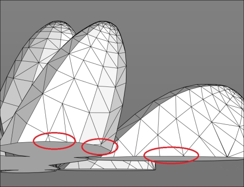
In order to create a perimeter for the slicer, some or all of the triangles that intersect the XY plane for the Z height may be used. In the following image, we can see the places where some triangles may be eliminated due to size or redundancy:
This is one reason why different slicers may produce different results. As shown in the following image, we can see a difference in the 39th Z height layer of this model:
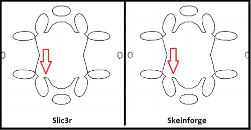
The narrow undercut of the perimeter is sharper in the Slic3r profile as opposed to the more rounded Skeinforge interpolation. This is a subtle difference, but it illustrates how there can be a difference between different slicer interpolations.
Another difference between slicer profiles will be how the extruder's actual path is generated. In the following figure, we can see the difference between Slic3r and Skeinforge:
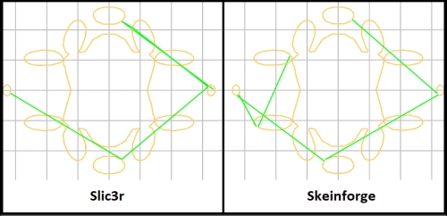
It's very unlikely that a difference in the actual movement path of the extruder will make a difference, unless the end and start of a Z height layer occurs in the same XY coordinate, and this creates a ridge in a detailed sensitive area of the model. Of course, this can be alleviated by selecting a random start point for each Z height in the slicer profile.
Repetier-Host, Pronterface, and other host software have good G-code viewers, but there is also a web browser G-code viewer that is useful. It is called G-code Visualizer. It's an open source web app that was created by Alex Utsyantsev, and it's available freely at http://gcode.ws/.


