


Coming around to 3D
We will be going over the basic understanding of the 3D work within this section. From coordinate systems to the makeup of how the 3D model is rendered, we will only go surface level to ensure that the foundations are firmly planted within you as you progress through this journey. By reading through this, you will be able to have a strong understanding of why Unity is displaying the items.
Coordinates Systems
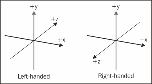
3D coordinate systems are not all the same in each application! Unity is a Left-handed (Figure 1.1) world coordinate system with +Y facing upwards. Looking in the image below you can visualize the difference from left-handed and right-handed systems:
While we work within these coordinate systems, you will see positions of objects represented in an array 3 values within parenthesis as follows:
(0, 100, 0)This represents (X, Y, Z) respectively. This is a good habit to get into as programming utilizes very similar syntax when writing out positions within the scripts. When we are talking about position, it is commonly referred as it’s “Transform”.
Local Space versus World Space
After understanding the world coordinates X, Y, Z, and that the very start of those coordinates start at 0 for each, represented with a (0, 0, 0). In the image below (Figure 1.2), where the colored lines meet is that 0,0,0 in the world. The cube has it’s own transform, which encompasses that object’s Transform, Rotation, and Scale:
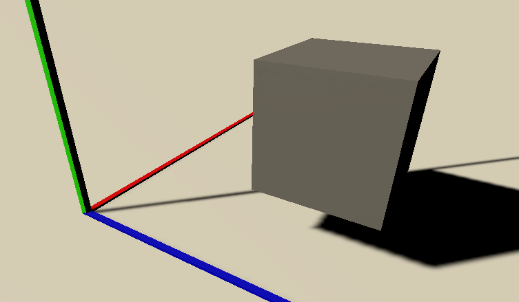
The cube in the image (Figure 1.2) is at (1, 1.5, 2). This is called world space as the item’s Transform is being represented through the world’s coordinates starting from (0, 0, 0):
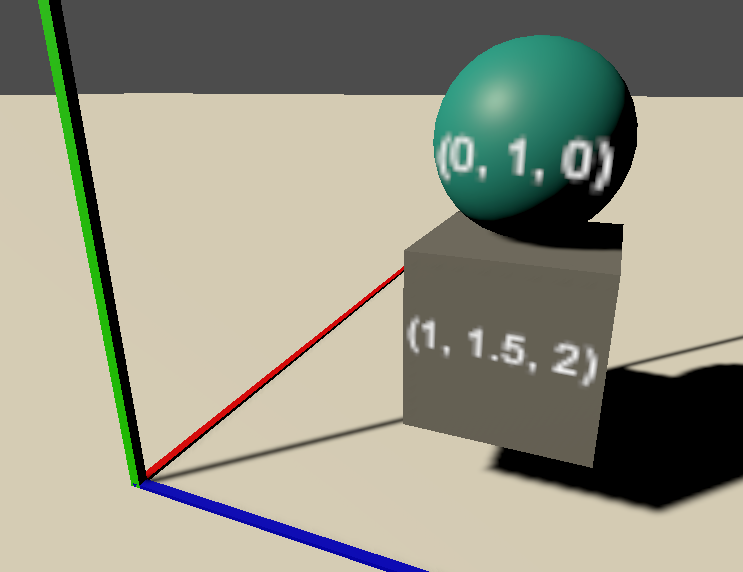
Now that we know the Cube’s transform is in relation to the world (0, 0, 0), we will not go over the parent-child relation which describes the local space. In the image above (Figure 1.3), the sphere is a child of the cube. The sphere’s local position is (0, 1, 0) in relation to the cube. Interestingly, if you now move the cube, the sphere will follow as it’s only offset from the cube and it’s transforms will remain (0, 1, 0) in relation to the cube.
Vectors
Traditionally, a vector is a unity that has more than one element. In a 3D setting, a vector 3 will look very similar to what we’ve worked with currently. (0, 0, 0) is a vector 3! Vectors are used in very many solutions to game elements and logic. Primarily the developer will normalize vectors so that way the magnitude will always equal 1. This allows developer to work with the data very easily as 0 is the start, .5 is halfway, and 1 is the end of the vector.
Cameras
Cameras are incredibly useful Objects! They humbly show us their perspective which allows our players to experience what we are trying to convey to them. As you may have guessed, a camera also has a transform just like all of game objects in the hierarchy. Cameras also have several parameters that can be changed to obtain different visual effects.
Different game elements and genres use cameras in different ways. Resident Evil using static cameras to give a sense of tension not knowing whats outside the window or around the corner, while Tomb Raider pulled the camera in close while she goes through caverns to give a sense of intimacy and emotional understanding with her face looking uncomfortable in tight spaces.
Cameras are essential to the experience you will be creating to your users, take time to play with them and learn compositional concepts to maximize the push of emotions in the players experience.
Faces, Edges, Vertices, and Meshes
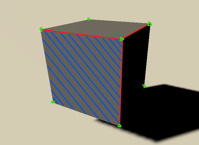
3D objects are made up of multiple parts as seen in Figure 1.4. Vertices, represented by the green circles, are points in space relative to the world (0, 0, 0). Each object has a list of these vertices and their corresponding connections. Two vertices connected make an edge, represented with a red line. A face is made when either 3 or 4 edges connect to make a triangle or a quad. Sometimes quads are called a plane when not connected to any other faces. When all of these parts are together, you have a mesh:
Materials, Textures, and Shaders
Now that you know how what a mesh is comprised of in all Digital Content Creation (DCC) tools, let’s look into how Unity displays that mesh to you. At the very base level is a shader. Shaders can be thought of as small programs, which have their own language, that help update the graphics pipeline so Unity can render the objects in your scene to your screen. You can think of the shader as a large template for materials to be created.
The next level up is materials. A material is a set of attributes which are defined by the shader to be manipulated, which helps show what the object looks like. Each rendering pipeline will have separate shaders. Built-in, Universal Rendering Pipeline (URP), and High Definition Rendering Pipeline. For this book, we are using the middle and most widely used URP.
Figure 1.5 shows an example of a material using the URP’s Standard Lit shader. This allows us to manipulate Surface options, inputs for that surface, and some advanced options. For now, let’s just talk about the Base Map, first item in the surface inputs section. The term “Base Map” is being used here as a combination of the “Diffuse/Albedo” and “Tint” together. Diffuse or Albedo is used to define the base color (Red) that will be applied to the surface, in this case, white. If you placed a texture into this map by either dragging a texture onto the square (Green) to the left of the base map or clicking on the circle (Blue) in between the box and the name. After that you can tint the surface with the color if there needs to be any adjustments:
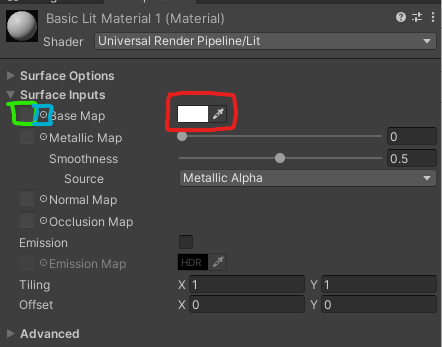
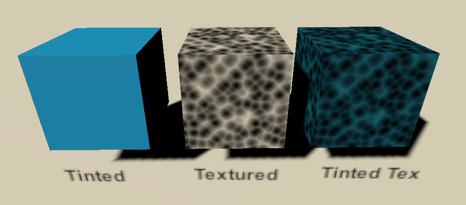
Figure 1.6 shows a simple example of what a cube would look like with a tint, texture, and the same texture with the tint changed. As we progress through the book, we will unlock more and more functions of materials, shaders and textures:
Textures can provide incredible detail for your 3D model. When creating a texture, the resolution is an important consideration. The first part of resolution that needs to be understood is “power of 2” sizes. A Power of 2 is as such:
2, 4, 8, 16, 32, 64, 128, 256, 512, 1024, 2048, 4096, etcThese numbers represent the pixel size for both width and height. There are cases that you may need to mix the sizes as long as they fit the Power of 2 scale. Examples are:
256×256
1024×1024
256×1024 (This is less common to see, but is valid)
The second consideration of resolution is the size itself. The easiest way to work through this consideration is thinking about how large the 3D object will be on your screen. If you have a 1920x1080 screen resolution, that is 1920 pixels wide by 1080 pixels tall. If the object in question is only going to be taking up 10% of the screen and rarely closer, you may consider a 256x256 texture. By contrast, if you are making an emotion character driven game where emotions from facial expressions matter, you may want a 4096x4096 or 4k texture on just the face during those cut scenes.
Rigid Body Physics
Unity assumes that every game object does not need to be evaluated every frame for physics. Unity uses Nvidia’s PhysX engine for it’s physics calculations. To get any calculated physics responses, the game object needs a Rigid Body component added.
By adding the Rigid Body component to the game object you are then adding some properties to the game object seen in the inspector Figure 1.7 below”:
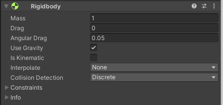
One unity unit of mass is equal to 1 kg of mass. This affects the physics decisions upon collisions. Drag units will attempt to reduce the velocity over time as friction. Angular Drag is similar, but constrained to only rotation speed. Using gravity either turns on or off gravity which is standard Earth gravity so the mass makes sense!
A thorough explanation of rigid body will be worked through in future chapters.
Collision Detection
A gameobject with a rigid body without any collision will not be fully utilizing the physics and with gravity turned on will just fall through the world. There are quite a few colliders to play with to best suit your games’ needs:
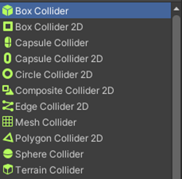
You are also welcome to add multiple colliders, basic options seen in Figure 1.8 above, to an object to best suit the shape of the gameobject. It is very common to see colliders on empty gameobjects that are children of the primary object to allow easy transformation of the colliders. We will see this in practice later in this book.

