Search icon CANCEL
Subscription
0
Cart icon
Your Cart (0 item)
Close icon
You have no products in your basket yet
Save more on your purchases! discount-offer-chevron-icon
Savings automatically calculated. No voucher code required.
Arrow left icon
All Products
Best Sellers
New Releases
Books
Videos
Audiobooks
Learning Hub
Newsletter Hub
Free Learning
Arrow right icon
timer SALE ENDS IN
0 Days
:
00 Hours
:
00 Minutes
:
00 Seconds
Arrow up icon
GO TO TOP
IoT Penetration Testing Cookbook

You're reading from   IoT Penetration Testing Cookbook Identify vulnerabilities and secure your smart devices

Arrow left icon
Product type Paperback
Published in Nov 2017
Publisher Packt
ISBN-13 9781787280571
Length 452 pages
Edition 1st Edition
Languages
Arrow right icon
Toc

Table of Contents (19) Chapters Close

Title Page
Credits
About the Authors
About the Reviewers
www.PacktPub.com
Customer Feedback
Dedication
Preface
1. IoT Penetration Testing FREE CHAPTER 2. IoT Threat Modeling 3. Analyzing and Exploiting Firmware 4. Exploitation of Embedded Web Applications 5. Exploiting IoT Mobile Applications 6. IoT Device Hacking 7. Radio Hacking 8. Firmware Security Best Practices 9. Mobile Security Best Practices 10. Securing Hardware 11. Advanced IoT Exploitation and Security Automation

Serial interfacing for embedded devices


Since we have already covered the basics of UART in the previous section, let's jump into how we can interface with UART interfaces.

Getting ready

We will start by looking at how to identify the pins once we have located the UART pinouts on a device.

The four pins that we are trying to find are as follows:

  • Tx
  • Rx
  • GND
  • Vcc

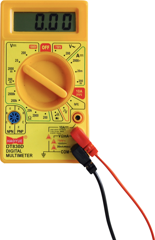
For this, we will use a multimeter, which can measure both voltage and current, thus acting as both a voltmeter and ammeter, hence the name, multimeter.

The following is what a multimeter looks like. Connect the probes as shown in the following image:

How to do it...

Once connected, let's go ahead and find the different UART pinouts as described in the upcoming steps.

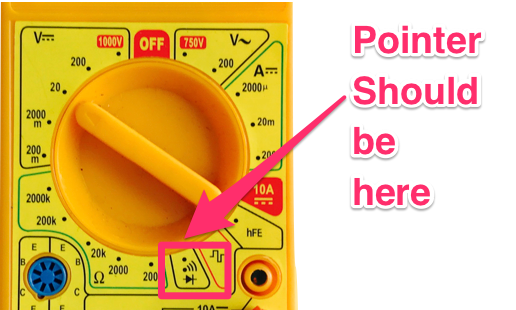
  1. Make sure that the pointer on the multimeter points to the speaker symbol, as shown in the following image:

Ensure that your device is turned off. Place the black probe on a ground surface-this could be any metallic surface on the device.

  1. Place the red probe on each of the four pads...
lock icon The rest of the chapter is locked
Register for a free Packt account to unlock a world of extra content!
A free Packt account unlocks extra newsletters, articles, discounted offers, and much more. Start advancing your knowledge today.
Unlock this book and the full library FREE for 7 days
Get unlimited access to 7000+ expert-authored eBooks and videos courses covering every tech area you can think of
Renews at $15.99/month. Cancel anytime
Visually different images