


Ohm's law
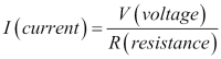
Electronics is all related to Ohm's law. This provides the relation between voltage, current, and resistance in a circuit. The law states that the current passing through a resistor is directly proportional to the applied voltage across it. In mathematical forms, it looks like this:
A simple way to remember and apply it according to either of the variables is the following triangle:
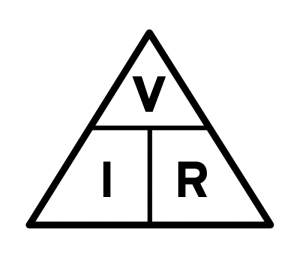
If we want to find the current, we cover I and we get V divided by R. The same goes for R: we cover it and we obtain V divided by I. Lastly, V will equal I multiplied with R. Let's now apply this knowledge to the following circuit:
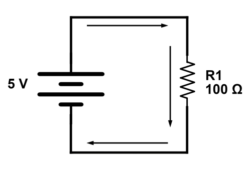
Here, we have one 5-volt voltage source in series with one resistor R1 with a resistance of 100 Ω. Because we have only one resistor, the total voltage across it will be equal to the voltage of the source, 5 V. We can now apply Ohm's law to find the current in the circuit:
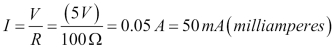
Remember that 1 ampere equals 1,000 milliamperes, represented by the unit mA.
Resistor configurations
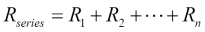
If we have more than one resistor in series, we can use the rule of series resistance. It states that any number of resistors in series can be replaced by only one, with the resistance equal to the sum of all replaced resistances. Mathematically, it is depicted as seen here:
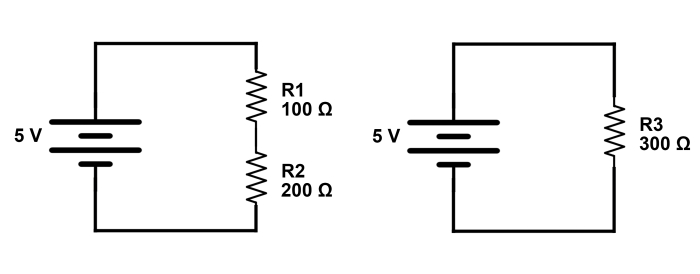
The following diagram shows the two resistors on the left in series R1 and R2. On the right, it shows the same circuit, but now with an equivalent resistor R3, which equals R1 + R2.
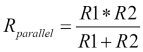
There is also the parallel resistor configuration. When we mount two or more resistors in parallel, the current is split among them. This results in a lower overall resistance. For two resistors, the formula looks like this:
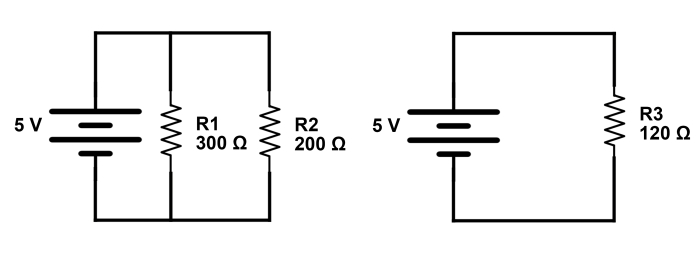
The following diagram proves just that. On the left we have the normal circuit with two resistors in parallel, and on the right we have the equivalent resistor value:
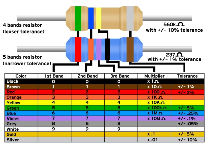
We can buy resistors with a variety of internal resistances. To easily determine what resistance a resistor has, a color code has been created. We can find the color stripes on every resistor. This is a helper diagram, which shows how to read the resistor color code:
You can find an online equivalent resistance calculator at http://calculator.tutorvista.com/equivalent-resistance-calculator.html.


