Connecting ESP8266 to Wi-Fi
Until now, you have installed and configured the Arduino IDE for ESP8266 and learned how to control a LED, read an analog input, and dim a LED.
Now it is time to connect ESP8266 to Wi-Fi. Include ESP8266's Wi-Fi library and set up the SSID name and the Wi-Fi password:
#include <ESP8266WiFi.h>
const char* ssid     = "your_wifi_name";
const char* password = "your_wifi_password";
In the setup section, Serial is started and configured to send data at 115200 bps; a 10 ms delay is added to allow Serial to finish and the GPIO from 12 to 15 are configured as output and their value is set to LOW:
void setup() {
Serial.begin(115200);
delay(10);
pinMode(12, OUTPUT);
pinMode(13, OUTPUT);
pinMode(14, OUTPUT);
pinMode(15, OUTPUT);

digitalWrite(12,LOW);
digitalWrite(13,LOW);
digitalWrite(14,LOW);
digitalWrite(15,LOW);
We will start by connecting to a Wi-Fi network:
Serial.println();
Serial.println();
Serial.print("Connecting to ");
Serial.println(ssid);
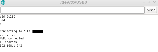
WiFi.begin(ssid, password); We wait until the status indicates that ESP8266 is connected to the Wi-Fi network. After this, the Wi-Fi connected message is displayed along with the IP address assigned to it by the router. Your router needs to be DHCP capable and have the DHCP feature enabled:
while (WiFi.status() != WL_CONNECTED) {
delay(500);
Serial.print(".");
  }

Serial.println("");
Serial.println("WiFi connected");
Serial.println("IP address: ");
Serial.println(WiFi.localIP());
}
In the loop section, the code checks to see whether the chip is connected to Wi-Fi and if this is true, the green LED will light on the Witty module:
void loop()
{
if(WiFi.status() == WL_CONNECTED)
digitalWrite(12, HIGH);
}
Note
As an exercise, you can light the RED led if there is no connectivity to your router, and the green LED otherwise.
The Serial Monitor will show the IP address assigned by the router, as follows: