Microprocessor without Interlocked Pipelined Stages (MIPS) was developed by MIPS technologies (formerly MIPS computer systems). Similar to ARM, at first, it was a 32-bit architecture with 64-bit functionality added later. Taking advantage of the RISC ISA, MIPS processors are characterized by low power and heat consumption. They can often be found in multiple embedded systems such as routers and gateways, and several video game consoles such as Sony PlayStation also incorporated them. Unfortunately, due to the popularity of this architecture, the systems implementing it became a target of multiple IoT malware families. An example can be seen in the following screenshot:
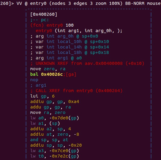
Figure 6: IoT malware targeting MIPS-based systems
As the architecture evolved, there were several versions of it, starting from MIPS I and going up to V, and then several releases of the more recent MIPS32/MIPS64. MIPS64 remains backward-compatible with MIPS32. These base architectures can be further supplemented with optional architectural extensions called Application Specific Extension (ASE) and modules to improve performance for certain tasks that are generally not used by the malicious code much. MicroMIPS32/64 are supersets of MIPS32 and MIPS64 architectures respectively, with almost the same 32-bit instruction set and additional 16-bit instructions to reduce the code size. They are used where code compression is required, and are designed for microcontrollers and other small embedded devices.
MIPS supports bi-endianness. The following registers are available:
- 32 GPRs r0-r31, 32-bit size on MIPS32 and 64-bit size on MIPS64.
- A special-purpose PC register that can be affected only indirectly by some instructions.
- Two special-purpose registers to hold the results of integer multiplication and division (HI and LO). These registers and related instructions were removed from the base instruction set in the release of 6 and now exist in the Digital Signal Processor (DSP) module.
The reason behind 32 GPRs is simple—MIPS uses 5 bits to specify the register, so this way, we can have a maximum of 2^5 = 32 different values. Two of the GPRs have a particular purpose, as follows:
- Register r0 (sometimes referred to as $0 or $zero) is a constant register and always stores zero, and provides read-only access. It can be used as a /dev/null analog to discard the output of some operation, or as a fast source of a zero value.
- r31 (also known as $ra) stores the return address during the procedure call branch/jump and link instructions.
Other registers are generally used for particular purposes, as follows:
- r1 (also known as $at): Assembler is temporary—used when resolving pseudo-instructions
- r2-r3 (also known as $v0 and $v1): Values—hold return function values
- r4-r7 (also known as $a0-$a3): Arguments—used to deliver function arguments
- r8-r15 (also known as $t0-$t7/$a4-$a7 and $t4-$t7): Temporaries—the first four can also be used to provide function arguments in N32 and N64 calling conventions (another O32 calling convention uses only r4-r7 registers; subsequent arguments are passed on the stack)
- r16-r23 (also known as $s0-$s7): Saved temporaries—preserved across function calls
- r24-r25 (also known as $t8-$t9): Temporaries
- r26-r27 (also known as $k0-$k1): Generally reserved for the OS kernel
- r28 (also known as $gp): Global pointer—points to the global area (data segment)
- r29 (also known as $sp): Stack pointer
- r30 (also known as $s8 or $fp): Saved value/frame pointer—stores the original stack pointer (before the function was called).
MIPS also has the following co-processors available:
- CP0: System control
- CP1: FPU
- CP2: Implementation-specific
- CP3: FPU (has dedicated COP1X opcode type instructions)
The majority of the main instructions were introduced in MIPS I and II. MIPS III introduced 64-bit integers and addresses, and MIPS IV and V improved floating-point operations and added a new set to boost the overall efficacy. Every instruction there has the same length—32 bits (4 bytes), and any instruction starts with an opcode that takes 6 bits. The following three major instruction formats supported are R, I, and J:
|
Instruction category
|
Syntax
|
Description
|
|
R-type
|
Specifies three registers: an optional shift amount field (for shift and rotate instructions), and an optional function field (for control codes to differentiate between instructions sharing the same opcode).
|
These instruction are used when all the data values used are located in registers.
|
|
I-type
|
Specifies two registers and an immediate value.
|
This group is used when the instruction operates with a register and an immediate value, for example, the ones that involve memory operations to store the offset value.
|
|
J-type
|
Has a jump target address after the opcode that takes the remaining bits.
|
They are used to affect the control flow.
|
For the FPU-related operations, the analogous FR and FI types exist.
Apart from this, several other less common formats exist, mainly coprocessors and extension-related formats.
In the documentation, registers usually have the following suffixes:
- Source (s)
- Target (t)
- Destination (d)
All instructions can be split into the following several groups depending on the functionality type:
- Control flow—mainly consists of conditional and unconditional jumps and branches:
- JR: Jump register (J format)
- BLTZ: Branch on less than zero (I format)
- Memory access—load and store operations:
- LB: Load byte (I format)
- SW: Store word (I format)
- ALU—covers various arithmetic operations:
- ADDU: Add unsigned (R format)
- XOR: Exclusive or (R format)
- SLL: Shift left logical (R format)
- OS interaction via exceptions—interacts with the OS kernel:
- SYSCALL: System call (custom format)
- BREAK: Breakpoint (custom format)
Floating-point instructions will have similar names for the same types of operations in most cases, for example, ADD.S. Some instructions are more unique such as Check for Equal (C.EQ.D).
As we can see here and later, the same basic groups can be applied to virtually any architecture, and the only difference will be in the implementation. Some common operations may get their own instructions to benefit from optimizations and, in this way, reduce the size of the code and improve the performance.
As the MIPS instruction set is pretty minimalistic, the assembler macros called pseudo-instructions also exist. Here are some of the most commonly used:
- ABS: Absolute value—translates to a combination of ADDU, BGEZ, and SUB
- BLT: Branch on less than—translates to a combination of SLT and BNE
- BGT/BGE/BLE: Similar to BLT
- LI/LA: Load immediate/address—translates to a combination of LUI and ORI or ADDIU for a 16-bit LI
- MOVE: Moves the content of one register into another—translates to ADD/ADDIU with a zero value
- NOP: No operation—translates to SLL with zero values
- NOT: Logical NOT—translates to NOR
PowerPC stands for Performance Optimization With Enhanced RISC—Performance Computing and sometimes spelled as PPC. It was created in the early 1990s by the alliance of Apple, IBM, and Motorola (commonly abbreviated as AIM). It was originally intended to be used in PCs and was powering Apple products including PowerBooks and iMacs up until 2006. The CPUs implementing it can also be found in game consoles such as Sony PlayStation 3, XBOX 360, and Wii, and in IBM servers and multiple embedded devices, such as car and plane controllers and even in the famous ASIMO robot. Later, the administrative responsibilities were transferred to an open standards body, Power.org, where some of the former creators remained members, such as IBM and Freescale. They then separated from Motorola and were later acquired by NXP Semiconductors, as well as many new entities. The OpenPOWER Foundation is a newer initiative by IBM, Google, IBM, NVIDIA, Mellanox, and Tyan, which is aiming to facilitate collaboration in the development of this technology.
PowerPC was mainly based on IBM POWER ISA and, later, a unified Power ISA was released, which combined POWER and PowerPC into a single ISA that is now used in multiple products under a Power Architecture umbrella term.
There are plenty of IoT malware families that have payloads for this architecture.
The Power ISA is divided into several categories; each category can be found in a certain part of the specification or book. CPUs implement a set of these categories depending on their class; only the base category is an obligatory one.
Here is a list of the main categories and their definitions in the latest second standard:
- Base: Covered in Book I (Power ISA User Instruction Set Architecture) and Book II (Power ISA Virtual Environment Architecture)
- Server: Covered in Book III-S (Power ISA Operating Environment Architecture – Server Environment)
- Embedded: Book III-E (Power ISA Operating Environment Architecture – Embedded Environment)
There are many more granular categories covering aspects such as floating-point operations and caching for certain instructions.
Another book, Book VLE (Power ISA Operating Environment Architecture – Variable Length Encoding (VLE) Instructions Architecture), defines alternative instructions and definitions intended to increase the density of the code by using 16-bit instructions as opposed to the more common 32-bit ones.
Power ISA version 3 consists of three books with the same names as Books I to III of the previous standard, without distinctions between environments.
The processor starts in the big-endian mode but can switch by changing a bit in the MSR (Machine State Register), so that bi-endianness is supported.
There are many sets of registers documented in Power ISA, mainly grouped around either an associated facility or a category. Here is a basic summary of the most commonly used ones:
- 32 GPRs for integer operations, generally used by their number only (64-bit)
- 64 Vector Scalar Registers (VSRs) for vector operations and floating-point operations:
- 32 Vector Registers (VRs) as part of the VSRs for vector operations (128-bit)
- 32 FPRs as part of the VSRs for floating-point operations (64-bit)
- Special purpose fixed-point facility registers, such as the following:
- Fixed-point exception register (XER)—contains multiple status bits (64-bit)
- Branch facility registers:
- Condition Register (CR)—consists of 8 4-bit fields, CR0-CR7, involving things like control flow and comparison (32-bit)
- Link Register (LR)—provides the branch target address (64-bit)
- Count Register (CTR)—holds a loop count (64-bit)
- Target Access Register (TAR)—specifies branch target address (64-bit)
- Timer facility registers:
- Time Base (TB)—is incremented periodically with the defined frequency (64-bit)
- Other special purpose registers from a particular category, including the following:
- Accumulator (ACC) (64-bit)—the Signal Processing Engine (SPE) category
Generally, functions can pass all arguments in registers for non-recursive calls; additional arguments are passed on the stack.
Most of the instructions are 32-bit size, only the Variable-Length Encoding (VLE) group is smaller in order to provide a higher code density for embedded applications. All instructions are split into the following three categories:
- Defined: All of the instructions are defined in the Power ISA books.
- Illegal: Available for future extensions of the Power ISA. An attempt to execute them will invoke the illegal instruction error handler.
- Reserved: Allocated to specific purposes that are outside the scope of the Power ISA. An attempt to execute them will either perform an implemented action or invoke the illegal instruction error handler if the implementation is not available.
Bits 0 to 5 always specify the opcode, and many instructions also have an extended opcode. A large number of instruction formats are supported; here are some examples:
- I-FORM [OPCD+LI+AA+LK]
- B-FORM [OPCD+BO+BI+BD+AA+LK]
Each instruction field has its own abbreviation and meaning; it makes sense to consult the official Power ISA document to get a full list of them and their corresponding formats. In the case of the previously mentioned I-FORM, they are as follows:
- OPCD: Opcode
- LI: Immediate field used to specify a 24-bit signed two's complement integer
- AA: Absolute address bit
- LK: Link bit affecting the link register
Instructions are also split into groups according to the associated facility and category, making them very similar to registers:
- Branch instructions:
- b/ba/bl/bla: Branch
- bc/bca/bcl/bcla: Branch conditional
- sc: System call
- Fixed-point instructions:
- lbz: Load byte and zero
- stb: Store byte
- addi: Add immediate
- ori: Or immediate
- Floating-point instructions:
- fmr: Floating move register
- lfs: Load floating-point single
- stfd: Store floating-point double
- SPE instructions:
- brinc: Bit-reversed increment