Search icon CANCEL
Subscription
0
Cart icon
Your Cart (0 item)
Close icon
You have no products in your basket yet
Save more on your purchases! discount-offer-chevron-icon
Savings automatically calculated. No voucher code required.
Arrow left icon
All Products
Best Sellers
New Releases
Books
Videos
Audiobooks
Learning Hub
Newsletter Hub
Free Learning
Arrow right icon
timer SALE ENDS IN
0 Days
:
00 Hours
:
00 Minutes
:
00 Seconds
Arrow up icon
GO TO TOP
Internet of Things with ESP8266

You're reading from   Internet of Things with ESP8266 Build amazing Internet of Things projects using the ESP8266 Wi-Fi chip

Arrow left icon
Product type Paperback
Published in Jul 2016
Publisher Packt
ISBN-13 9781786468024
Length 226 pages
Edition 1st Edition
Tools
Arrow right icon
Author (1):
Arrow left icon
Marco Schwartz Marco Schwartz
Author Profile Icon Marco Schwartz
Marco Schwartz
Arrow right icon
View More author details
Toc

Table of Contents (20) Chapters Close

Internet of Things with ESP8266
Credits
About the Author
About the Reviewer
www.PacktPub.com
Preface
1. Getting Started with the ESP8266 FREE CHAPTER 2. First Projects with the ESP8266 3. Cloud Data Logging with the ESP8266 4. Control Devices from Anywhere 5. Interacting With Web Services 6. Machine-to-Machine Communications 7. Sending Notifications from the ESP8266 8. Controlling a Door Lock from the Cloud 9. Building a Physical Bitcoin Ticker 10. Wireless Gardening with the ESP8266 11. Cloud-Based Home Automation System 12. Cloud-Controlled ESP8266 Robot 13. Building Your Own Cloud Platform to Control ESP8266 Devices Index

Hardware configuration


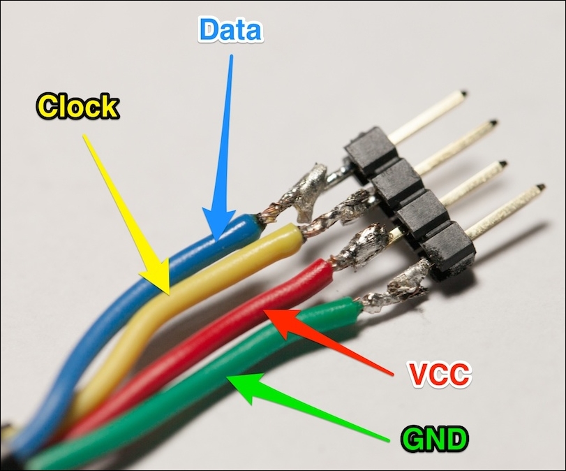
We are now going to assemble the different parts of this project. First, you need to get familiar with the different pins of the SHT10 sensor:

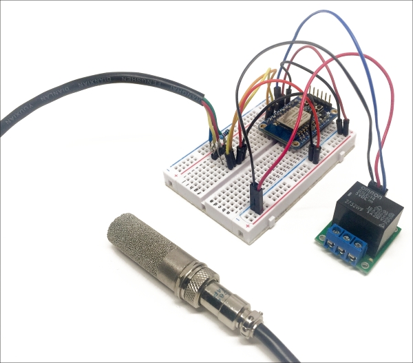
Once that's done, put the sensor's connector on the breadboard. Also connect the VCC and GND pins of the ESP8266 to the breadboard red and blue power lines.

Next, connect the sensor's VCC and GND pins to the red and blue power rails, respectively. Then, connect the data pin to pin number 4 of the ESP8266, and the clock pin to pin number 5. Finally, add the 10K Ohm pull-up resistor between the data and the VCC pins of the sensor.

For the relay, simply connect GND to the blue power rail, VCC to the red one, and finally the SIG pin to pin number 15 of the ESP8266.

This is the final result:

However, we are not done yet; we need something to measure! You can now insert the sensor inside the soil, for example in the pot of a plant inside your home, or in your garden outside. This is how I inserted it to monitor one of the plants in my...

lock icon The rest of the chapter is locked
Register for a free Packt account to unlock a world of extra content!
A free Packt account unlocks extra newsletters, articles, discounted offers, and much more. Start advancing your knowledge today.
Unlock this book and the full library FREE for 7 days
Get unlimited access to 7000+ expert-authored eBooks and videos courses covering every tech area you can think of
Renews at £13.99/month. Cancel anytime
Visually different images