Search icon CANCEL
Subscription
0
Cart icon
Your Cart (0 item)
Close icon
You have no products in your basket yet
Save more on your purchases! discount-offer-chevron-icon
Savings automatically calculated. No voucher code required.
Arrow left icon
All Products
Best Sellers
New Releases
Books
Videos
Audiobooks
Learning Hub
Newsletter Hub
Free Learning
Arrow right icon
timer SALE ENDS IN
0 Days
:
00 Hours
:
00 Minutes
:
00 Seconds
Arrow up icon
GO TO TOP
Building a Home Security System with Raspberry Pi

You're reading from   Building a Home Security System with Raspberry Pi Build your own sophisticated modular home security system using the popular Raspberry Pi board

Arrow left icon
Product type Paperback
Published in Dec 2015
Publisher
ISBN-13 9781782175278
Length 190 pages
Edition 1st Edition
Arrow right icon
Author (1):
Arrow left icon
 Poole Poole
Author Profile Icon Poole
Poole
Arrow right icon
View More author details
Toc

Table of Contents (16) Chapters Close

Building a Home Security System with Raspberry Pi
Credits
About the Author
About the Reviewers
www.PacktPub.com
Preface
1. Setting Up Your Raspberry Pi FREE CHAPTER 2. Connecting Things to Your Pi with GPIO 3. Extending Your Pi to Connect More Things 4. Adding a Magnetic Contact Sensor 5. Adding a Passive Infrared Motion Sensor 6. Adding Cameras to Our Security System 7. Building a Web-Based Control Panel 8. A Miscellany of Things 9. Putting It All Together Index

Anti-tamper circuits


If you take a closer look at our system, you might realize that depending on whether you are detecting normally open or normally closed sensor switches, it is possible to tamper with the sensor channel by simply cutting the wire. So, in the case of a normally open switch, it wouldn't activate the monitoring system if the wires were cut, as it would always appear to be open, even if the switch was closed.

To mitigate this, most alarm systems feature a 4-core wiring system to connect the sensor devices to the main control board—two cores are used to connect the sensor and two are used to create an anti-tamper loop, which then itself forms a sensor input for monitoring.

4-core alarm cable

Take a look at the following circuit so that you see what I mean:

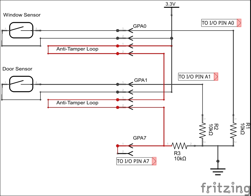
In this circuit, we have two sensors: one for monitoring a window and one for monitoring a door. These are connected to the I/O BUS A inputs, 0 and 1 (or GPA0 and GPA1, as we like to call them). As before, they are pulled down...

lock icon The rest of the chapter is locked
Register for a free Packt account to unlock a world of extra content!
A free Packt account unlocks extra newsletters, articles, discounted offers, and much more. Start advancing your knowledge today.
Unlock this book and the full library FREE for 7 days
Get unlimited access to 7000+ expert-authored eBooks and videos courses covering every tech area you can think of
Renews at £13.99/month. Cancel anytime
Visually different images