Search icon CANCEL
Subscription
0
Cart icon
Your Cart (0 item)
Close icon
You have no products in your basket yet
Save more on your purchases! discount-offer-chevron-icon
Savings automatically calculated. No voucher code required.
Arrow left icon
All Products
Best Sellers
New Releases
Books
Videos
Audiobooks
Learning Hub
Newsletter Hub
Free Learning
Arrow right icon
timer SALE ENDS IN
0 Days
:
00 Hours
:
00 Minutes
:
00 Seconds
Arrow up icon
GO TO TOP
Arduino for Secret Agents

You're reading from   Arduino for Secret Agents Transform your tiny Arduino device into a secret agent gadget to build a range of espionage projects with this practical guide for hackers

Arrow left icon
Product type Paperback
Published in Nov 2015
Publisher
ISBN-13 9781783986088
Length 170 pages
Edition 1st Edition
Languages
Tools
Concepts
Arrow right icon
Author (1):
Arrow left icon
Marco Schwartz Marco Schwartz
Author Profile Icon Marco Schwartz
Marco Schwartz
Arrow right icon
View More author details
Toc

Table of Contents (16) Chapters Close

Arduino for Secret Agents
Credits
About the Author
About the Reviewer
www.PacktPub.com
Preface
1. A Simple Alarm System with Arduino FREE CHAPTER 2. Creating a Spy Microphone 3. Building an EMF Bug Detector 4. Access Control with a Fingerprint Sensor 5. Opening a Lock with an SMS 6. Building a Cloud Spy Camera 7. Monitoring Secret Data from Anywhere 8. Creating a GPS Tracker with Arduino 9. Building an Arduino Spy Robot Index

Opening and closing the lock


Now that we managed to actually control the relay and the LED by sending text messages to the FONA shield, we can connect the actual lock. This last step of the project is optional as you already tested the main functionality of the project and connecting the electronic door lock is a bit more technical. This is an image of the lock that I used:

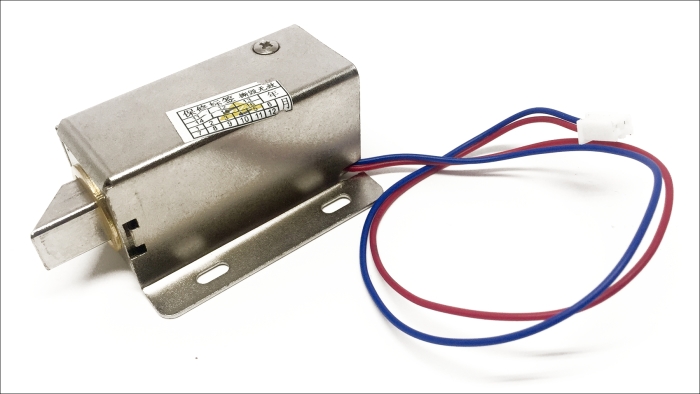
First, you'll need to cut the JST connector from the electronic lock in order to be able to connect it the breadboard. I soldered some 2-pin header at the end of the electronic lock to make it compatible with my breadboard.

Then, you'll need to assemble the remaining optional components on the breadboard, as shown in the following schematic:

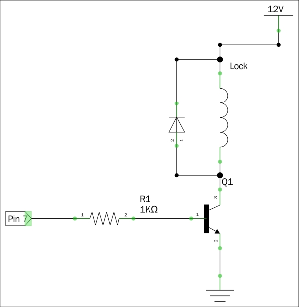
Let's see how to assemble these components together. First, place all the components on the breadboard. Then, connect the digital pin 7 of the Arduino board to the base of the transistor via the 1K Ohm resistor. Also, connect the emitter of the transistor to the ground of the project...

lock icon The rest of the chapter is locked
Register for a free Packt account to unlock a world of extra content!
A free Packt account unlocks extra newsletters, articles, discounted offers, and much more. Start advancing your knowledge today.
Unlock this book and the full library FREE for 7 days
Get unlimited access to 7000+ expert-authored eBooks and videos courses covering every tech area you can think of
Renews at £13.99/month. Cancel anytime
Visually different images