In this article by Daniela Cristiana Docan, author of the book Learning ArcGIS For Desktop, we will look at the ArcGIS editing tools to create and edit feature shapes and attributes. By the end of this article, you will learn the following:
- Spatially adjusting vector data to real-world units
- Editing feature shapes and attributes using ArcMap editing tools
(For more resources related to this topic, see here.)
Editing features in a geodatabase file
In this article, we will work with three primary features’ geometries: point, line, and polygon. A point feature is defined by a single pair of x, y coordinates. The line and polygon features are defined by vertices and segments.
The vertices represent ordered x, y coordinate pairs that form a feature's shape. The coordinates of a vertex also include the M (measure) and Z (elevation) values.
A segment connects only two vertices. A line with two or more segments is called polyline. In ArcGIS, the line and polygon feature classes can store single or multipart features. A multipart feature is composed of two or more disconnected shapes that have only one record in the feature class attribute table. A simple point feature class cannot store multipart features, but a multipoint feature class can store multipoint features.
In the editing process, the shape of a feature can be modified by moving, adding, or deleting the vertices that form its sketch. A sketch displays the location of vertices and segments that define the feature's shape.
There are six main steps in the feature's shape editing process, which are as follows:
- Adding the data in a map document
- Starting an edit session
- Setting a feature template and snapping properties to edit the layer's feature geometry
- Creating a new feature by adding a new sketch or select an existing feature and display its sketch
- Editing a feature’s shape—moving, deleting, or inserting one or more vertices
- Saving the feature edits and stopping the edit session
Using spatial adjustment
In this section, we will perform a spatial adjustment for two feature classes imported from a CAD file that don't have a real-world coordinate system associated.
We will use the Affine Transformation method that requires at least three displacement links. A displacement link defines the source and destination coordinates used by the transformation method. Before starting any spatial adjustment, be sure that the horizontal accuracy of the destination coordinates is at least the same or better as the horizontal accuracy of source coordinates.
Follow these steps to perform a spatial adjustment in the ArcMap application:
- Start the ArcMap application and open the existing map document, SpatialAdjustment.mxd, from <drive>:LearningArcGISChapter05.
- In Table Of Contents, right-click on the Polyline layer and navigate to Properties | Source. Note that there is no projection information associated with the layer. Close the Layer Properties window. Repeat the step for the Polygon layer.
First, we will add a basemap for the Brussels city from ArcGIS Online.
Check whether ArcGIS for Desktop is connected to ArcGIS Online.
- In the Standard toolbar, from the drop-down menu next to Add Data, click on Add Data from ArcGIS Online. Search for the brusselsdata and select Brussels - Orthophoto 2012. Click on Details to read the information from the Description tab. Click on the yellow button called Add Data, as shown in the following screenshot:

- Drag the Brussels - Orthophoto 2012 basemap layer to the bottom of Table Of Contents.
- Right-click on the Brussels-Orthophoto 2012 basemap layer and go to Properties | Source. Inspect the resolution and the coordinate system of the orthophoto map. The layer's coordinate system is Belge_Lambert_1972002C, and the map projection is Lambert_Conformal_Conic.
Second, we will use Spatial Adjustment tools to move the Polyline and Polygon layers to their correct coordinates using the Brussels-Orthophoto 2012 basemap layer as the destination coordinate space, as shown in the following screenshot:

- Add the Spatial Adjustment and Editor toolbars from Customize | Toolbars. To apply a spatial adjustment to the Polyline and Polygon layers, you must start the editing session. In the Editor toolbar, navigate to Editor | Start Editing.
- In the Spatial Adjustment toolbar, go to Spatial Adjustment | Set Adjust Data. Check All features in these layers[SI1] and make sure both the Polyline and Polygon layers are selected. Click on OK.
- Then, in the Spatial Adjustment toolbar, go to Spatial Adjustment | Adjustment Methods. We will use the default transformation method called Transformation-Affine.
- Go to the Bookmarks menu and select Manage Bookmarks. Click on the Load button and add Source_points.dat and Destination_points.dat from <drive>:LearningArcGISChapter05.
- Keep Bookmarks Manager open and inspect Source and Destination for all the seven points by selecting the bookmark and clicking on Zoom To button. When finished, close the Bookmarks Manager window.
Instead of adding the displacement links manually, you can load them through a links file.
- In the Spatial Adjustment toolbar, click on Link Table. Go to Spatial Adjustment | Links|Open Links File, navigate to <drive>:LearningArcGISChapter05, and select DisplacementLinks.txt. Now, click on Open. Link Table is automatically updated with seven coordinate pairs. You can modify or delete the individual links.
- In the Spatial Adjustment toolbar, navigate to Spatial Adjustment | Adjust. Note the RMS Error value: 4.9 meters. For a dataset with the reference scale of 1:15,000, an RMS value of 4.9 meters is a reasonable one. The assumed reference scale and the resulting RMS value should be mentioned in metadata file (at Item Description | Resource | Lineage). Next, close the Link Table.
If you want add the displacement links manually, you should set up the snapping environment by checking Vertex Snapping in the Editor | Snapping toolbar.
- As you can note, the Polyline and Polygon layers were both transformed to match the Brussels-Orthophoto 2012 coordinate space. Inspect the results. In the Editor toolbar, navigate to Editor | Save Edits to save the spatial adjustment applied to the Polyline and Polygon layers.
In the second part of the exercise, we will define the reference system for the Brussels_CADToGeodatabase feature dataset.
- Open the Catalog window and connect to the <drive>:LearningArcGISChapter05 folder. Expand World.gdb. Then, right-click on Brussels_CADToGeodatabase and go to Properties | XY Coordinate System. In the Search text box, type belge. Navigate to Projected Coordinate Systems | National Grids | Europe and select Belge Lambert 1972. Click on the Add To Favorites button. Then, click on Apply.
You will see a warning message that tells you that it will modify the existing object as it cannot acquire a schema lock. However, you cannot modify the reference system while you are in an open edit session.
- Click on OK twice to close all dialog windows. In the Editor toolbar, navigate to Editor | Stop Editing. Repeat the last step to define the reference system for the Brussels_CADToGeodatabase feature dataset. Note that the Polyline and Polygon feature classes automatically inherit the feature dataset's reference system.
- When finished, save your map document as MySpatialAdjustment.mxd to <drive>:LearningArcGISChapter05.
You can find the results of this exercise at <drive>:LearningArcGISChapter05 ResultsSpatialAdjustment.
Unlock access to the largest independent learning library in Tech for FREE!
Get unlimited access to 7500+ expert-authored eBooks and video courses covering every tech area you can think of.
Renews at £15.99/month. Cancel anytime
Editing features
In this section, you will learn how to create a new feature class from an existing one using the Export Data tool in the ArcMap application. Next, you will explore different edit tools to create new features by splitting or combining the existing features. In the end, you will learn how to modify the feature's shape by adding, moving, and deleting vertices on its sketch.
Before you start editing a feature sketch, you should always set the snapping properties, such as the snap type or snapping tolerance value. Snapping helps you create coincidence during the editing process. Snapping allows you to move the mouse pointer exactly to a vertex, edge, start point, or endpoint of a feature, when the pointer location is within a predefined distance of them. This distance is called snapping tolerance. ArcMap calculates the value of the snapping tolerance for you, but you can change it and specify your own value.
Follow these steps to start editing features using the ArcMap application:
Start the ArcMap application and open a new map document. Open the Catalog window, and navigate to..Chapter05EditingFeaturesWorld.gdb.
- Expand the Europefeature dataset. Select the EuropeCities_10k feature class and drag it on the ArcMap map display. The map shows the Paris and Brussels cities at a scale of 1:10,000.
- In Table Of Contents, right-click on theEuropeCities_10k layer and select Open Attribute Table. Dock the Table window to the bottom of the map display by dragging and dropping it on the down arrow of the blue centered target.
- Click on the Table Options button in the upper-left corner and select Select by Attributes. Build the following expression: CITIES = 'Bruxelles/Brussel'. Then, click on Apply and Close. Note that 32945 records are selected in the attribute table and on the map display. We will save these selected features in a new feature class called Brussels.
- Right-click on the EuropeCities_10k layer and select Data | Export Data. For Export, accept the Selected features option. Click on the browser button, make sure you are in the ..Chapter05EditingFeaturesWorld.gdbEurope folder, and type Brussels for the name of the feature class. Click on the No button to not add the exported data to map display as a layer. In the Catalog window, the Europe feature dataset is updated with your new polygon feature class. Hide the Catalog window by clicking on the Auto hide button. Then, close the Table window.
Next, we will change the projection of the Brussels feature class and save it into the Brussels feature dataset.
- In the Standard toolbar, click on the ArcToolbox tool. Navigate to ArcToolbox | Data Management Tools | Projections and Transformations and select Projection. Set the following parameters:
- Input Dataset or Feature Class: ..EditingFeaturesWorld.gdbEuropeBrussels
- Output Dataset or Feature Class: ..EditingFeaturesWorld.gdbBrusselsBrusselsCity
- Output Coordinate System: Belge_Lambert_1972
- Geographic Transformation: Belge _1972_To_ETRS_1989_2
- Click on OK. Click on No to not add the exported data to the map display as a layer. Hide the ArcToolbox window by clicking on the Auto hide button.
- On the Standard toolbar, click on the New tool to open a new map document. In the New Document dialog window, for Default geodatabase for this map, click on the browser button and navigate to <drive>:LearningArcGISChapter05EditingFeaturesWorld.gdb. Click on Add and OK. Finally, click on No to not save the changes from the last map document.
- Add the BrusselsCity and Buildings feature classes from the Brussels feature dataset in ArcMap by dragging them on the map display.
- Change the BrusselsCity symbol to Hollow, Outline Width to 1.5 , and Outline Color to Medium Coral Light. Label the features with the OBJECTID field's values. Change the label to Medium Coral Light.
- Change the Buildings symbol to Hollow, Outline Width to 1.5, and Outline Color to Solar Yellow. Label the Buildings features with the OBJECTID field's values.
- Navigate to Add Data | Add Data From ArcGIS Online to add two aerial photos of Brussels: Brussels -Othotophoto 2004 and Brussels -Othotophoto 2012. In Table Of Contents, drag Brussels -Othotophoto 2004 to the bottom of list.
- From the Bookmarks menu, select Manage Bookmarks. Click on the Load button, navigate to <drive>:LearningArcGISChapter05, and select the EditingFeaturesAttributes.dat ArcGIS Place file. Click on Open. These bookmarks will help us identify particular study areas in the next exercises. Click on Close.
- When finished, save your map document as MyEditingFeatures.mxd at <drive>:LearningArcGISChapter05EditingFeatures.
In the next steps, we will start editing the building footprints from the Buildings layer. These buildings were digitized using an aerial photo from 2004 (Brussels -Othotophoto 2004) as layer reference. We will update the features to reflect the changes that were made from 2004 to 2012 using Brussels -Othotophoto 2012 as the reference layer.
- First, we will set the Buildings layer as the only selectable layer in the map. At the top of Table Of Contents, click on the List By Selection button. Both the BrusselsCity and Buildings layers will be selectable. Click on the Selectable button next to the BrusselsCity layer to move it to the Not Selectable list. Return to the List By Drawing Order layers’ list mode.
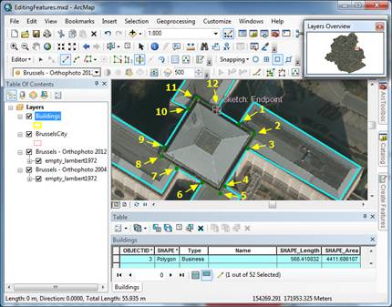
- From Bookmarks, select Edit 1. You will divide a feature into five separate features, as shown in the following screenshot:
- In Table Of Contents, right-click onthe Buildings layer and select Open Attribute Table. Dock the Table window to the bottom of the map display.
- First, we will start an edit session and set the snapping properties. If necessary, add the Editor toolbar. In the Editor toolbar, go to Editor | Start Editing.
- Second, we will create a feature template. If the Create Features window isn't open, you should navigate to Editor | Editing Windows | Create Features. As the BrusselsCity and Buildings layers reference two feature classes that are stored in the same workspace called World.gdb, the Create Features window displays the default feature templates for both of them.
- In the Create Features window, double-click on the Buildings template to open the Template Properties window. Inspect the information for the template displays. For Description, type Brussels buildings . For Default Tool, accept Polygon. Click on OK to update the Buildings feature template. At the bottom of the Created Features window, in the Construction Tools list, make sure that the Polygon tool is selected.
- Next, we will use the default snapping environment to enable snapping to feature vertices. From the Editor menu, navigate to Snapping | Snapping Toolbar. In the Snapping toolbar, turn off all snapping types, except the Vertex Snapping button. During the edit process, your mouse pointer will be moved exactly only to the vertices of a feature.
ArcMap allows you to activate the classic snapping environment if you need more control to snapping properties, such as the individual type of snapping on each editable layer or snapping tolerance units (pixels or map units). To activate the classic snapping, in the Editor menu, navigate to Editor | Options | General and take a look at Use classic snapping. From the Editor menu, navigate to Snapping | Snapping Window to manage the individual snapping on layers. To change the snapping tolerance units, go to Editor | Snapping | Options.
- In the Tools toolbar, click on the Select Feature tool and select the building shown in the preceding screenshot. At the bottom of the Table window, click on the Show selected records button to see only the selected building’s record.
- In the Editor toolbar, select the Cut Polygons tool. Note that another tool called Straight Segment is selected. You will cut the polygon feature using a multipart polyline. Move the pointer close to the start point (1) indicated before to see the SnapTip called Buildings: Vertex. Click on the 1 point to add the first vertex of the segment. Click on the 2 point and again on the 3 point. Then, right-click on the third vertex and select Finish Part.
If you want to delete a vertex, right-click on it and select Delete Vertex.
You can use the Zoom in, Zoom out, and Pan tools while you are splitting the polygon, but you have to select the Cut Polygons tool again to continue adding vertices.
- Click on the 4, 5, and 6 points, as shown in the preceding screenshot. Right-click on the sixth vertex and select Finish Part. Repeat the steps for the rest of points. Right-click on the twelfth vertex (Sketch: Enpoint) and select Finish Sketch.
- Five new features are created and selected on the map display. In the Table window, note that the Buildings feature class table is updated with five new building records corresponding to the five polygons on the map display. To unselect the new features on the map, use the Clear Selected Features tool on the Tools toolbar.
- To save your edits to the data, select Save Edits in the Editor menu.
In the next steps, we will continue to update the buildings by erasing the two buildings that have been demolished since 2010, and we will merge the two existing features to represent a larger commercial building, as shown in the following screenshot:

- We will continue to use the Buildings feature template. From Bookmarks, select Edit 2. Add the Effects toolbar on the map display and select Brussels-Orthophoto 2012 from the drop-down list of layers. Select the Swipe button. Then, click on the map display and drag to see the differences between the two ortophoto maps.
- Use the Select Feature tool and the Shift key to select two buildings that have the following OBJECTID values: 53 and 52. Right-click on the map display and select Delete. You have a second option of removing them from the Buildings layer using the Delete Selected tool in the Table window.
During an edit session, you should use the Edit tool to select a feature by clicking on it. As we don't set Sticky move tolerance at Editor | Options | General, we have to use the Select Feature tool to prevent the accidental moving of the selected features.
- Use the Select Feature tool to select the buildings with the OBJECTID values 51 and 54. In the Table window, inspect the attribute values of the building with the ID 51.
- In the Editor toolbar, navigate to Editor | Merge. In the Merge dialog window, click on the first feature Industrial (Buildings). The selected feature flashes on the map. As the first feature in the list is the larger one that has a name, we would like to keep its attribute values. Click on OK.
- In the Table window, note that the OBJECTID, Type, and Name values were inherited from the previous selected feature. Instead, the SHAPE_Length and SHAPE_Area fields are updated by ArcMap.
In the next steps, we will reshape the building with OBJECTID 51, as shown in the following screenshot:

- To edit the building shape, you must display its sketch. In the Editor toolbar, select the Edit Tool button, double-click on the building to select it, and display the feature's sketch, as shown in the preceding screenshot. The Edit Vertices mini toolbar is automatically added on the map.
- Drag and draw a box over the four vertices as shown before. Move the pointer over one of the selected vertices until it turns in a compass arrow, right-click, and select Delete Vertices. If you make a mistake, use the Undo Delete tool from the Standard toolbar and repeat the step. To erase the vertices of two or more sketches, you can also draw a box over the vertices using the Delete Vertex tool from the Edit Vertices mini toolbar.
- Click away from the selected feature to unselect it and see the changes. In the Editor toolbar, select the Edit Tool button again and double-click on the building to display the feature's sketch. On the Edit Vertices toolbar, select Add Vertex. Click on the line segment and add two vertices, as shown in the preceding screenshot.
- Click on the first new vertex (1) to select it. Move the pointer over the selected vertex until it turns in a compass arrow. Drag and drop the vertex to the new location.
- Now, click on the second new vertex (2) to select it. You will move this feature's vertex to an exact x, y location. Right-click on vertex and select Move To Fist; then, click on the down arrow next to the X box and check whether Meter is selected. In the X box, select and delete the existing value. Type 154266.227 and press the Tab key. For Y, type 172231.383 and press the Enter key. Note that the vertex has moved to the exact location. Press the F2 key to finish the sketch.
- Even if your feature shape changes in your map document, the edits of the data is not save in your feature class. To store the updated date in your file geodatabase, you must save your edits during an edit session or when you stop the edit session. In the Editor toolbar, navigate to Editor | Save Edits. Saving your map document does not save the data edits to your geodatabase.
In the last steps, we will move three adjacent buildings and reshape one of them, as shown in the following screenshot:

- From Bookmarks, select Edit 4. In the Editor toolbar, click on the Edit tool. Drag and draw a box over the three buildings, as shown in the preceding screenshot. Note that the Start and End points of the box do not touch the polygon’s features. This way, you can select three adjacent buildings with the Edit tool without accidentally producing small position moves.
- To move all the buildings 5 meters on the Y axis, from the Editor toolbar, go to Editor | Move. In the Delta X, Y window, type 5 in the second box and press the Enter key. All the three buildings will shift 5 meters on the Yaxis.
- Next, we will adjust the shape of a building. In the Tool toolbar, click on the Clear Selected Features tool to unselect the buildings. With the Edit tool, select the building with ID 45 and then click on the Reshape Feature tool on the Editor toolbar.
- Click on the 1 point to add the first vertex of the line segment. Click on the 2 point to add the second vertex, and then click on the 3 point to add the third vertex. Press the F2 key to finish the sketch. Inspect the results. Unselect the building and save the edits. In the Editor toolbar, stop the edit session by navigating to Editing | Stop Editing.
- When finished, save your changes to the map document. Leave the MyEditingFeatures map document open to continue working with map topology in the next recipe.
You can find the results at <drive>:LearningArcGISChapter05 ResultsEditingFeaturesEditingFeatures.mxd.
Summary
In this article, we identified the main steps in the editing process. You learned how to modify the existing features and add new features. Also, we explored different ArcMap instruments to edit the coincident features—that is, using the Auto-Complete Polygons and map topology tools.
Resources for Article:
Further resources on this subject:

 United States
 Great Britain
 India
India
 Germany
 France
 Canada
 Spain
Spain
 Brazil
 Australia
 South Africa
 Thailand
 Switzerland
 Slovakia
 Luxembourg
 Hungary
 Romania
 Denmark
 Ireland
 Estonia
 Belgium
 Italy
Italy
 Finland
 Cyprus
 Lithuania
 Latvia
 Malta
Malta
 Netherlands
 Portugal
 Slovenia
 Sweden
 Argentina
 Colombia
 Ecuador
 Indonesia
 Mexico
 New Zealand
 Norway
 South Korea
 Taiwan
 Turkey
 Czechia
 Austria
 Greece
 Isle of Man
 Bulgaria
 Japan
Japan
 Philippines
 Poland
 Singapore
 Egypt
Egypt
 Chile
Chile
 Malaysia